or an interactive light “piano.”
I wanted to get out of my comfort zone for the final project of my first ever engineering class. I explored capacitive sensing in this project to design a circular light “piano” that lights up depending on the sensor you press. Check out the original documentation.
ideas
When I started looking for final project ideas, I knew I wanted to utilize capacitive touch to prepare for my final FabAcademy project. My first idea was a capacitive touch and conductive fabric plush game controller, but I knew that I wasn’t fully interested in the project. I also worried that using conductive fabric would not teach me as much about capacitive touch as other projects could. I was excited by the project in that it would let me make a game controller to play the games that I love in a new and different way. My second idea was a capacitive touch Arduino piano keyboard. My worries with this project was that it was too simple, and that it would not be challenging enough for me. However, I was excited that making the project would allow me to make a version of an instrument that was so special to me. My third idea was an capacitive touch LED and MIDI circular-piano project, named Eclipse. My worries with this project was that it would take too long for me to make, and that I would not be able to code the LED string lights and the MIDI, but I wanted to take up on the challenge. I was most excited to make this project because it would give me an opportunity to take on a new challenge of making a relatively complex project that I had never experienced before. I expected that the most challenging part of the project would be implementing the capacitive sensors.
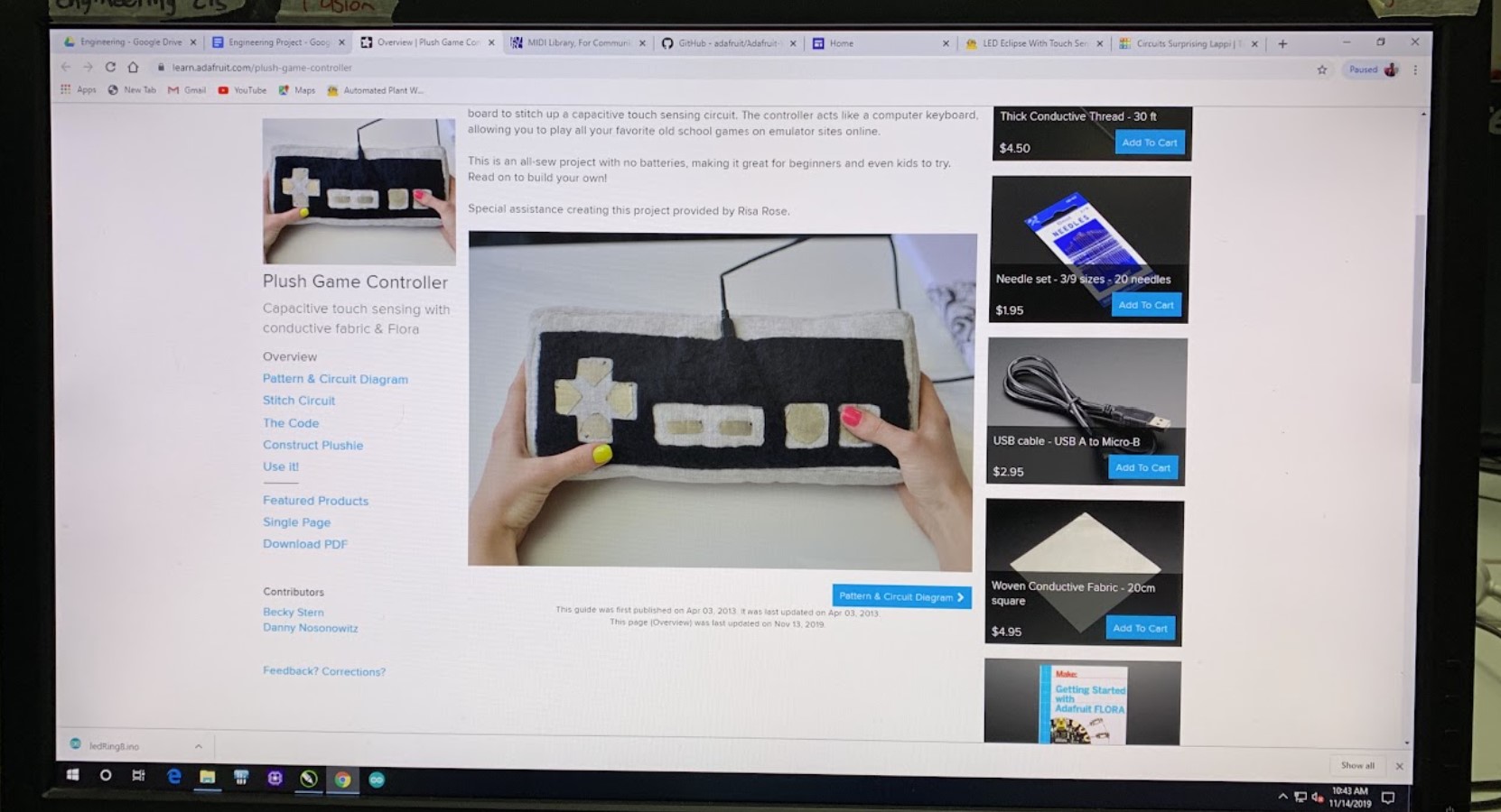
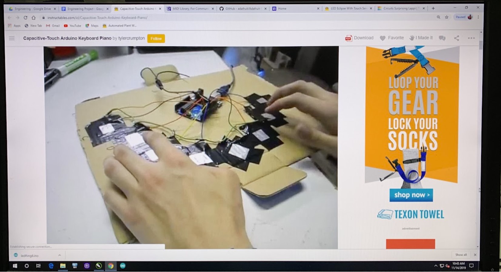
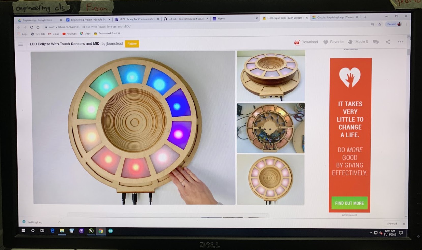
I chose my third idea, the Eclipse project, because it seemed like a really interesting project with the sleekest design out of the three projects. I also thought that the project would teach me a lot about capacitive sensors and how to use them. For me, a successful project would uniquely light up depending on which capacitive sensor was pressed. I used the Instructables project version, made by user jbumstead (which can be found at https://www.instructables.com/id/LED-Eclipse-With-Touch-Sensors-and-MIDI/), as inspiration and reference.
supplies
For this project, I used the following materials and supplies:
The supplies that were already at school included:
- Cardboard
- White acrylic
- Plywood
- Breadboard
- Arduino Uno
- 10 Female to Male jumper wires
- 10 long black wires
- 10 5.5k Ohm Resistors
- 1 1M Ohm Resistor
- USB extension
- Wood glue
- Super glue
- LED Strips
The materials that needed to be additionally bought were:
- Wooden dowels - ($10.00)
- I used the following tools:
- Laser cutter (for cardboard, I used the setting of 20 speed, 100 frequency, and 100 power.)
- PCB Milling machine
- Soldering iron
- Table saw (I used the table saw to cut any of the thicker wooden dowels)
I also used the following programs:
- Arduino
- CorelDraw
Luckily, since we had most of the materials at school, I only needed to buy the wooden dowels, costing us $10.00 without tax.
As for final design specifications, the base part of my project was approximately 18 inches in diameter, and the top part of the project was 14 inches in diameter. The height of project was approximately 5 inches tall. Made of mainly cardboard, the Eclipse is also made of a bit of acrylic and plywood, as well as circuit boards for the capacitive sensors.
planning and designing
When I first started making my project, I made a vague plan for myself. I planned to finish a sketch of the product with specifications and to finish designing and cutting each of the 30 layers by the second week of working (Nov 25), and to finish the coding and testing out the LEDs by the third week (Dec 2). Finally, I planned to finish the capacitive touch prototyping and testing by the next week (Dec 9), leaving the last week to add on vinyl stickers to cover the capacitive sensors and any other small design changes.
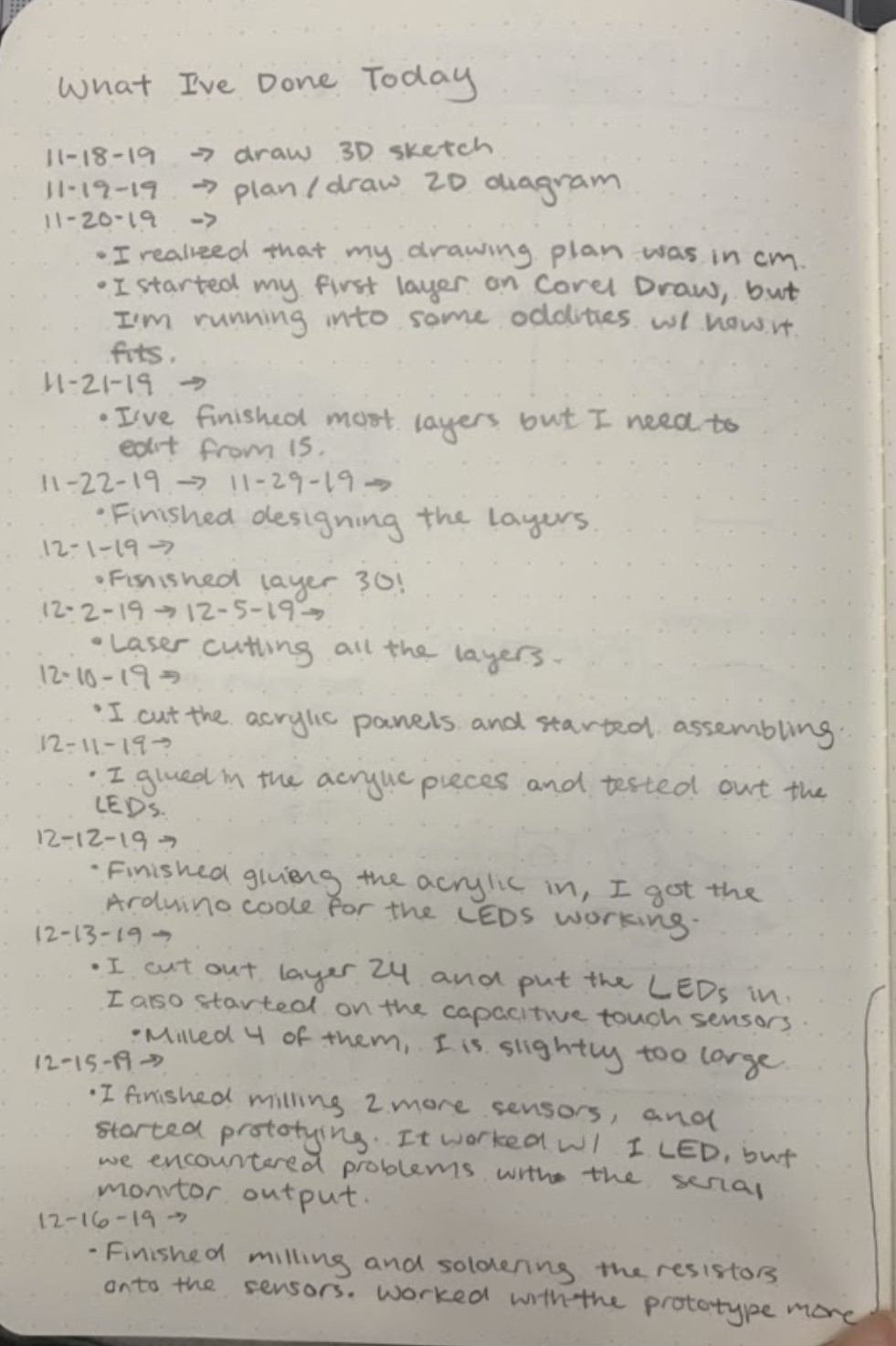
I did not meet my deadlines. I underestimated how much time it would take to design and cut each layer, as well as the amount of time it would take to make a proof of concept before implementing it into the actual project. Designing and cutting each layer ended up taking almost three weeks to finish, and afterwards cutting the acrylic and getting the LEDS to work took another week. I ended up using the final week to finalize my project and make a proof of concept for my capacitive sensors before implementing them into the base of my project. As a result, I had no time to add vinyl stickers on the capacitive sensors and could not add small design details to my project. The pictures below are pictures of my journal entries, showing that what I actually accomplished did not match the pace that I planned.
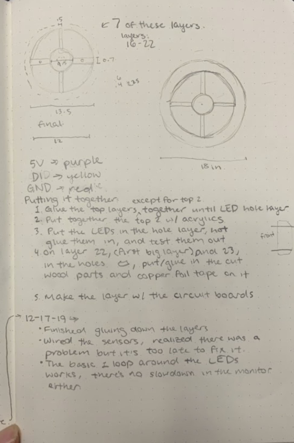
I first started off my project by sketching out what my vision for it would be. I decided to do this because sketching out designs has helped me visualize my project before. It gives me a better understanding of what I am making. I spent a class period sketching out a 3D full version of the project, along with other various layers of the design. I tried to make sure I was content with the measurements of the project. The pictures below show some of my sketches.
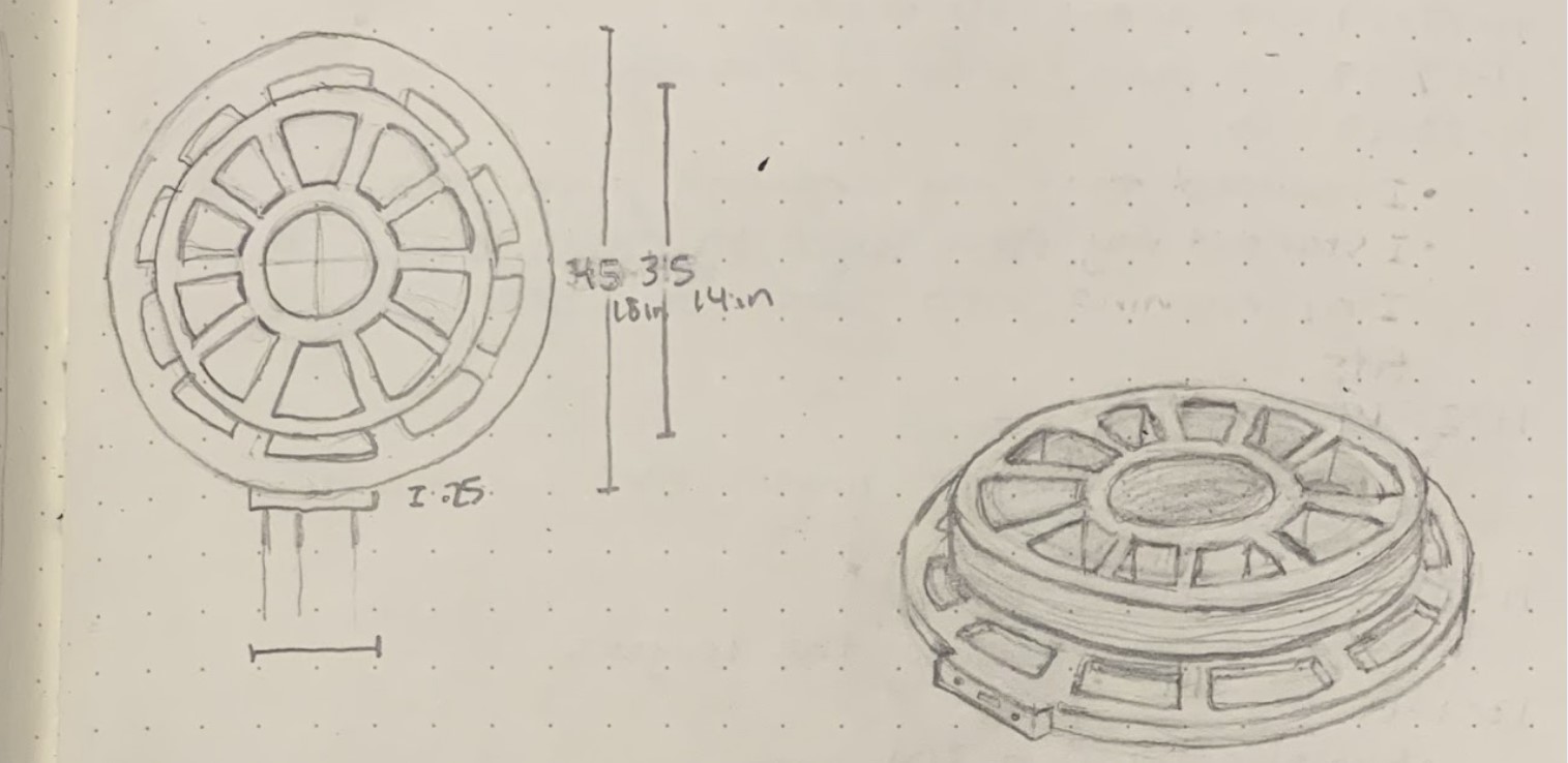
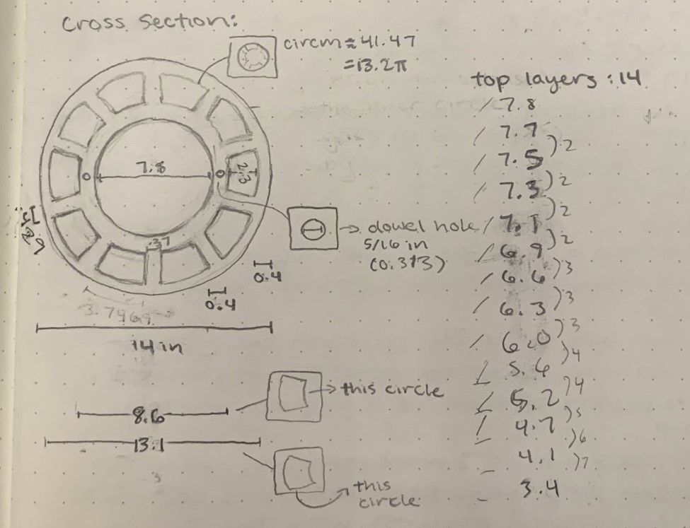
I then recreated these sketches in Corel Draw more carefully, making sure that I kept precise measurements and specifications. I created one file with 30 layers, each of which were specifically made with the original project’s design in mind. The picture below is what I used as a reference to recreate all the layers; most of the layers look rather similar to those of the original project, but specific measurements and design details are a little different.
You can find my version of these layers at the link https://drive.google.com/open?id=1JO5MBlL0xTXSsXQBNZ7rFOK2YKvIZ2mY (If you are apart of the Charlotte Latin School domain and you have Corel Draw downloaded. If you cannot access the link, some of the pictures below will give you a glimpse of what a couple of the layers looked like.
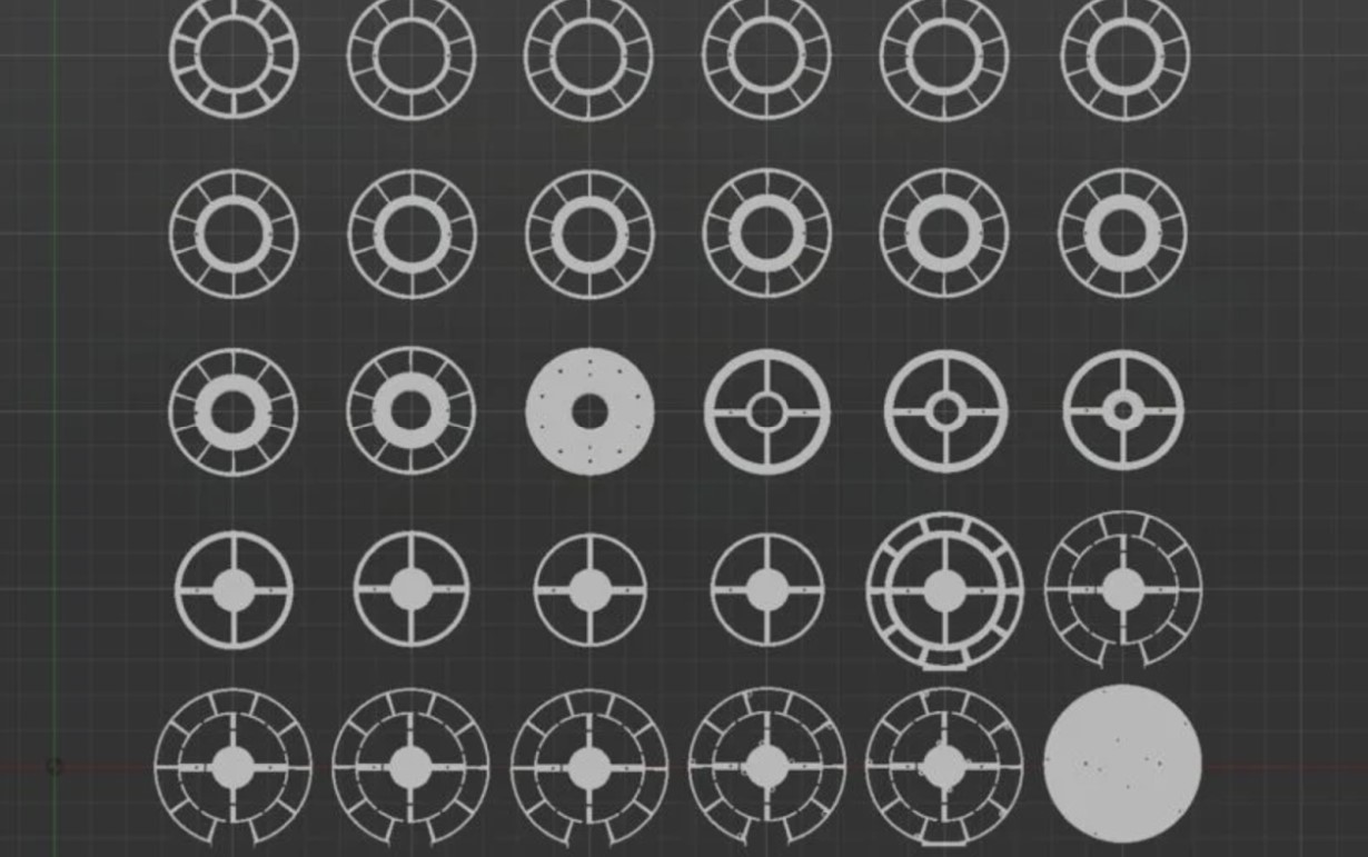
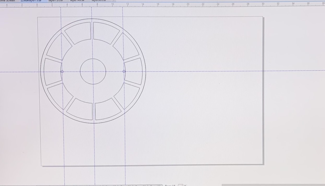
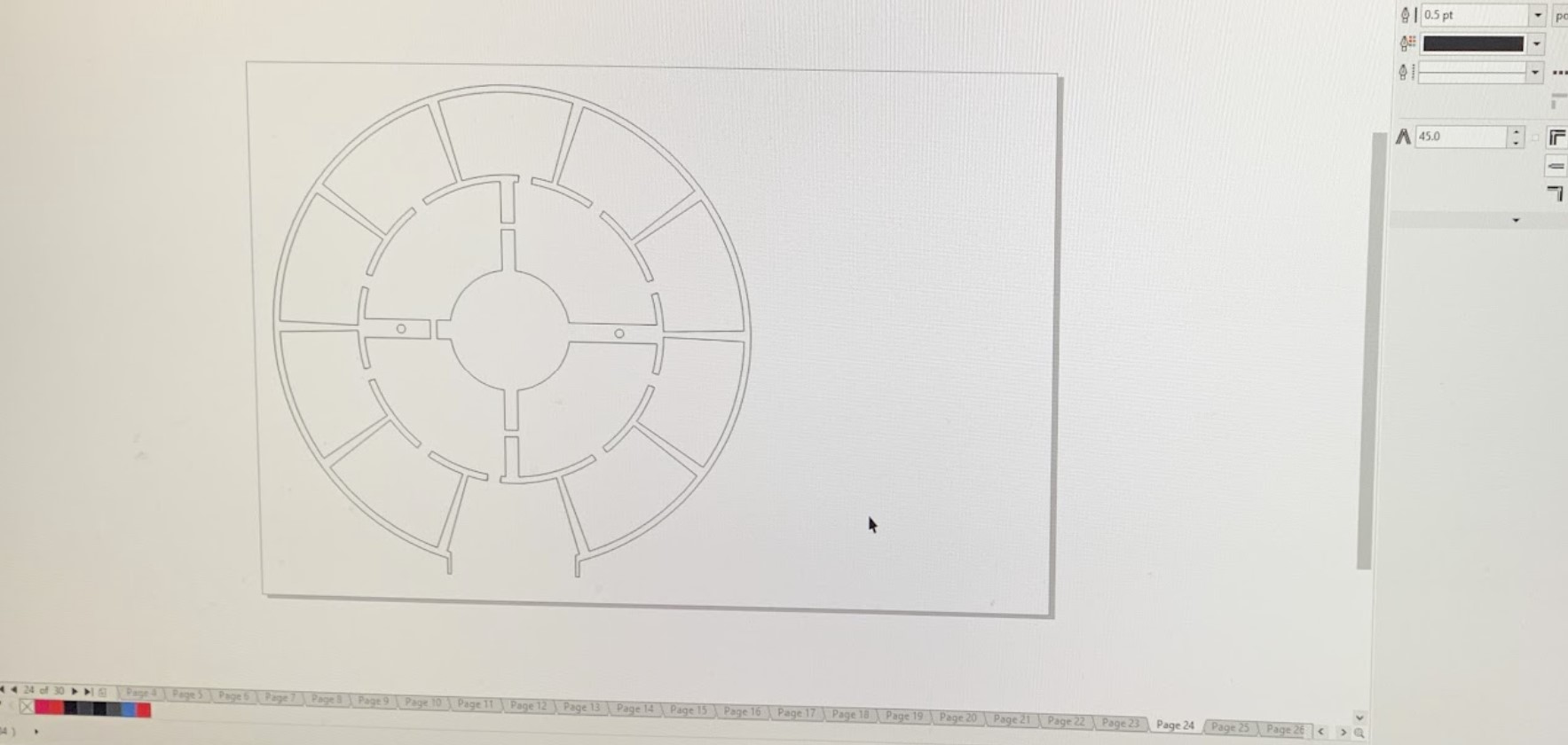
In order to design each layer, I started off making a circle of a specific diameter. For the first 14 layers, the diameters were the same, and for the last 22 the diameters were also the same, although they had a different value. The diameter for the first 14 layers ended up being the diameter of the smaller circle of the next 22 layers. In each of the first 14 layers, the design was identical, except for the inner circle, whose diameter shrunk by an average of 0.3 inches per layer. The other layers were designed using similar methods.
finalizing project
cutting and assembling
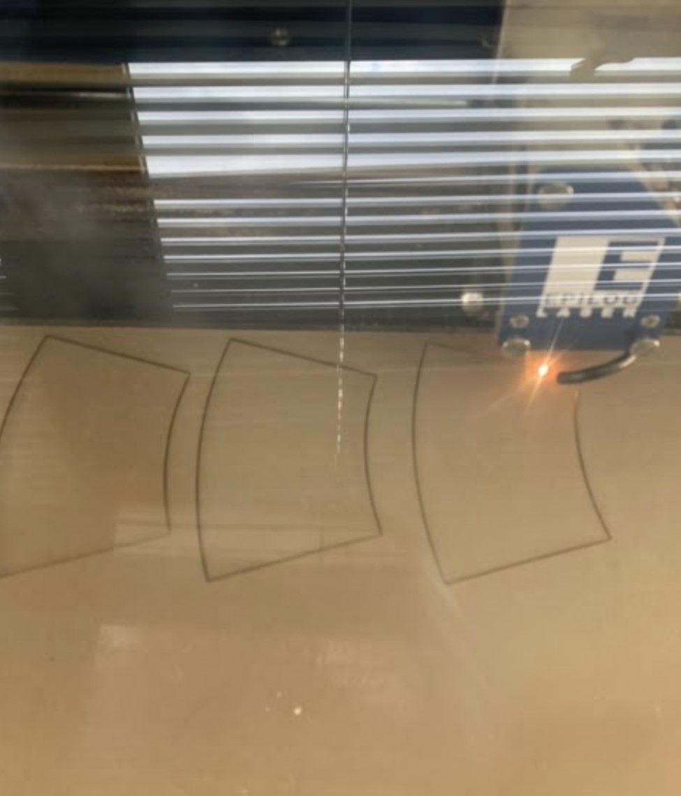
After all the layers were designed, I decided to laser-cut them in cardboard. Not only did we not have enough plywood for me to use 36 sheets of, but I also thought it would be easier to work with cardboard in general as it is more flexible. I only used one sheet of 1/8” plywood for layer 23, as it would make the look of the project more diverse. The pictures below show a couple of the laser cuts in process.
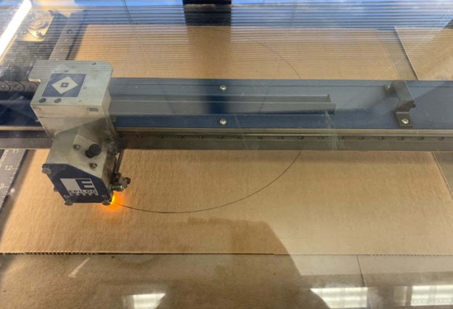
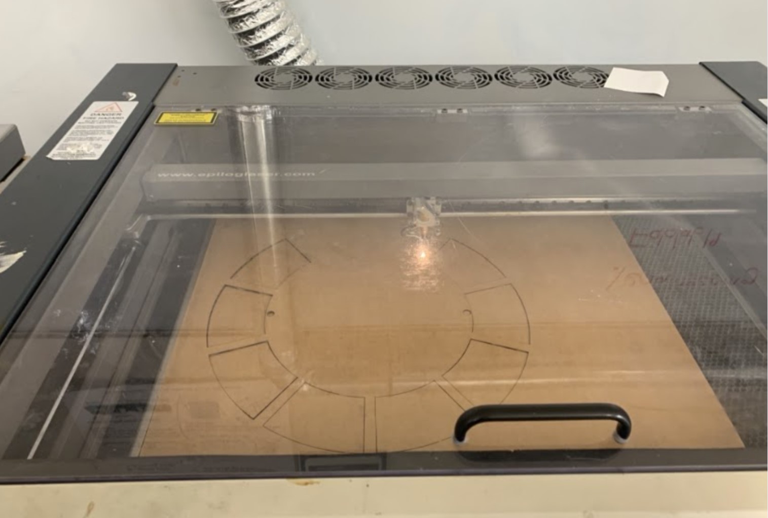
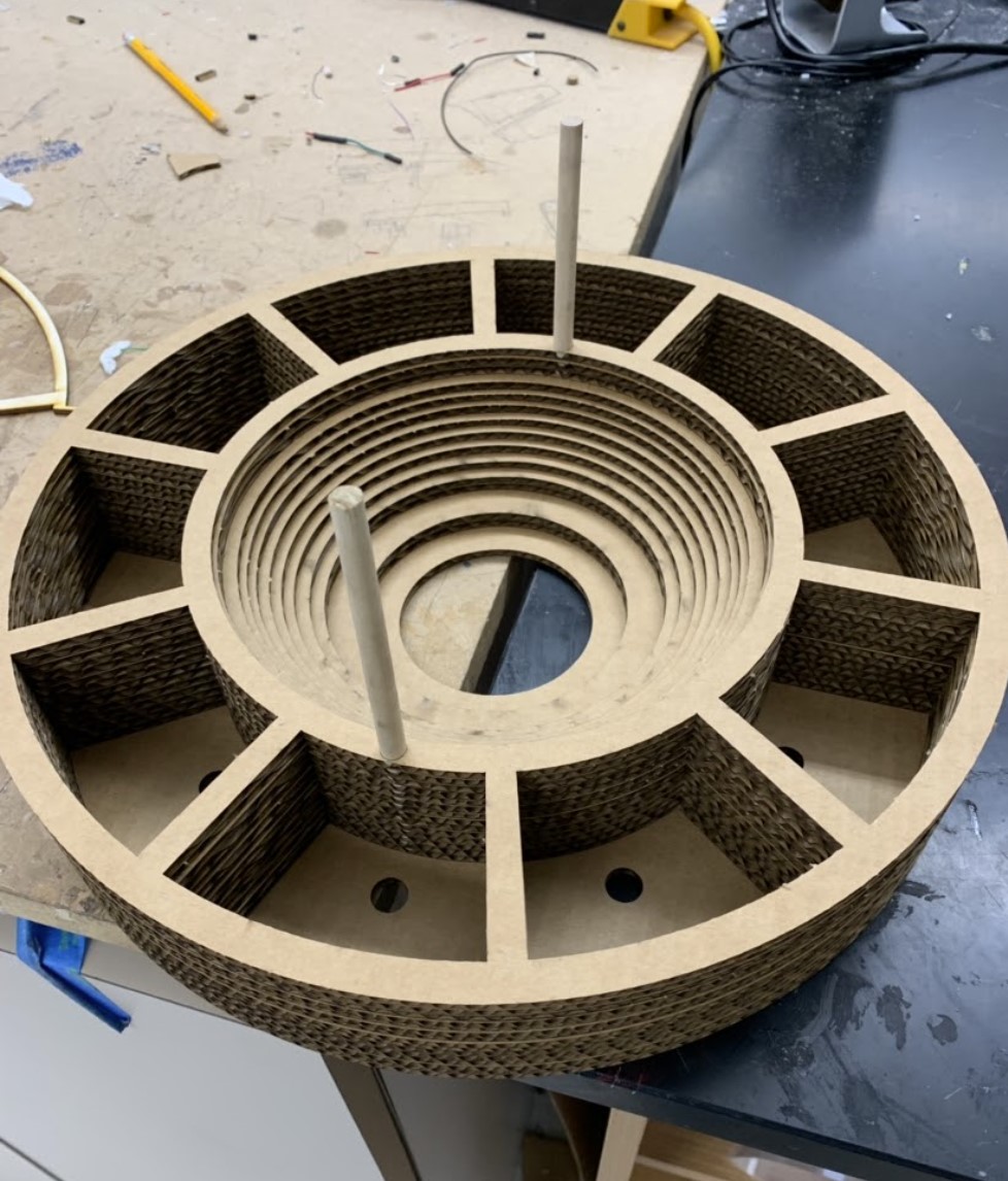
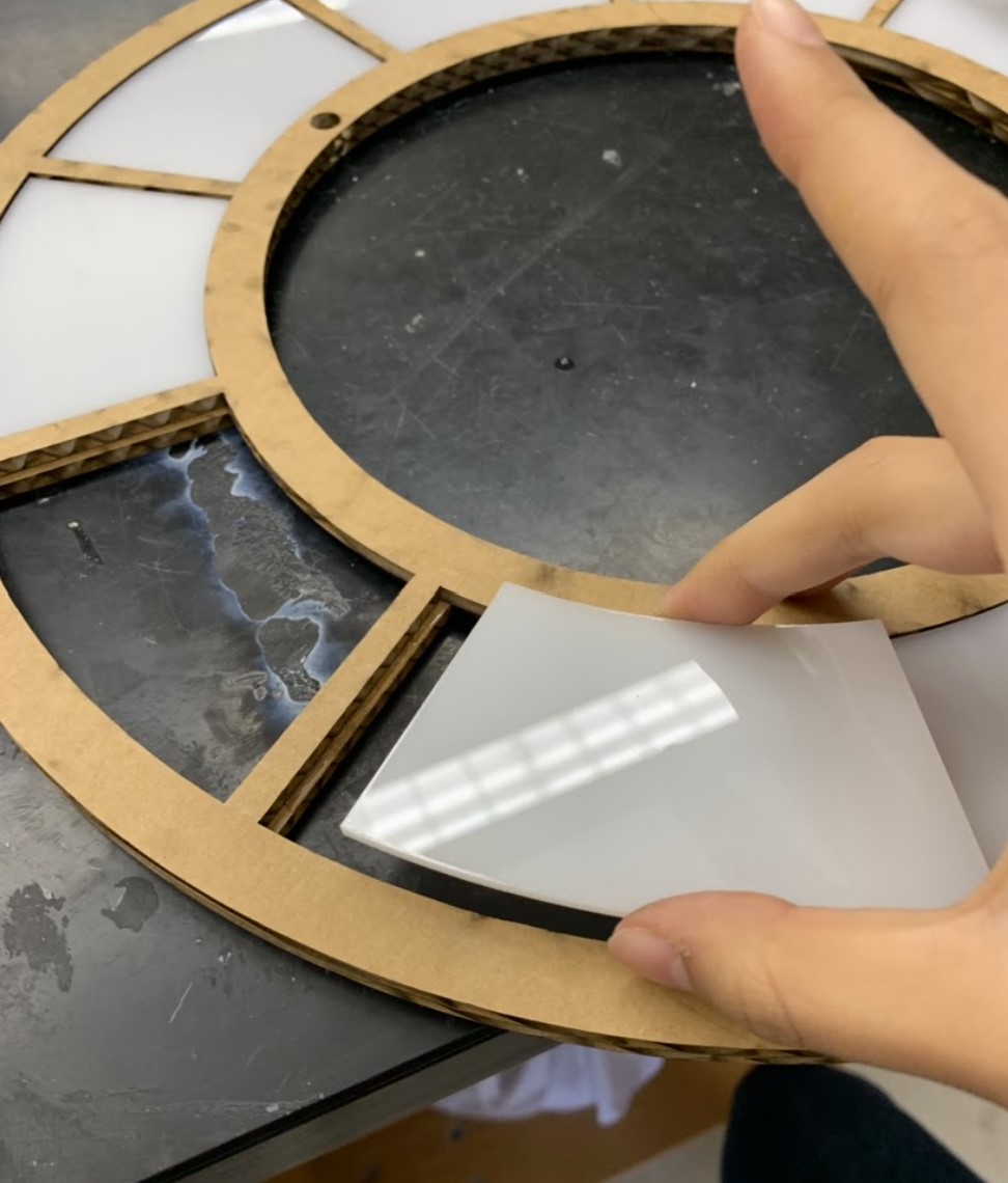
After I laser-cut the layers, I started assembling and wood-glueing together layers 3-14 first. I used two wooden dowels of 5/16” to make sure that each layer was centered. This step is shown in the picture below on the left. I then glued together the first two layers, and laser-cut the curved sections in acrylic. I superglued the acrylic onto layer 2. This step is shown in the two pictures below to the right. The first one is the laser-cutting of the white acrylic pieces and the second is the glueing.
Afterwards, I glued the two sections I had together, with layer 2 facing upwards.
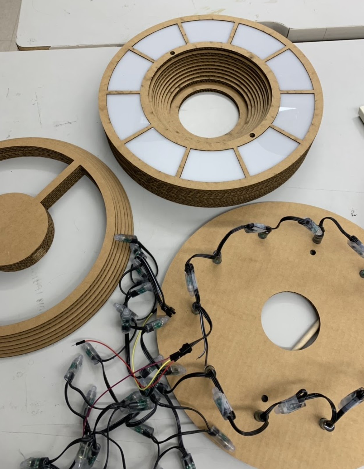
Then I got the LED string lights. I pushed every other LED into each hole in layer 15, taping the LEDs that weren’t in a hole to its wire.
I also went ahead and glued together layers 16-22. I ended up cutting away the section of the layer with the holes for the wooden dowels, as I realized that they would get in the way of the string LED wires. I then used three male to male jumper wires and attached them to the 5V, DI, and GND pins from the female end of the LEDs.
The first picture below shows each of these parts.
wiring and coding the led’s
After glueing the layer 15 section with the LEDs to layers 16-22, I tested out a simple Arduino code for the LEDs. As this was my first time using string LED lights, it took a few minutes to figure out what was going on. After a little while though, I was able to manipulate the code as needed. The second picture shows the testing of the code and wiring of the LEDs. The third picture shows the same testing of the code and wiring, just with a different LED color and including the first 14 layers, diffusing the light.
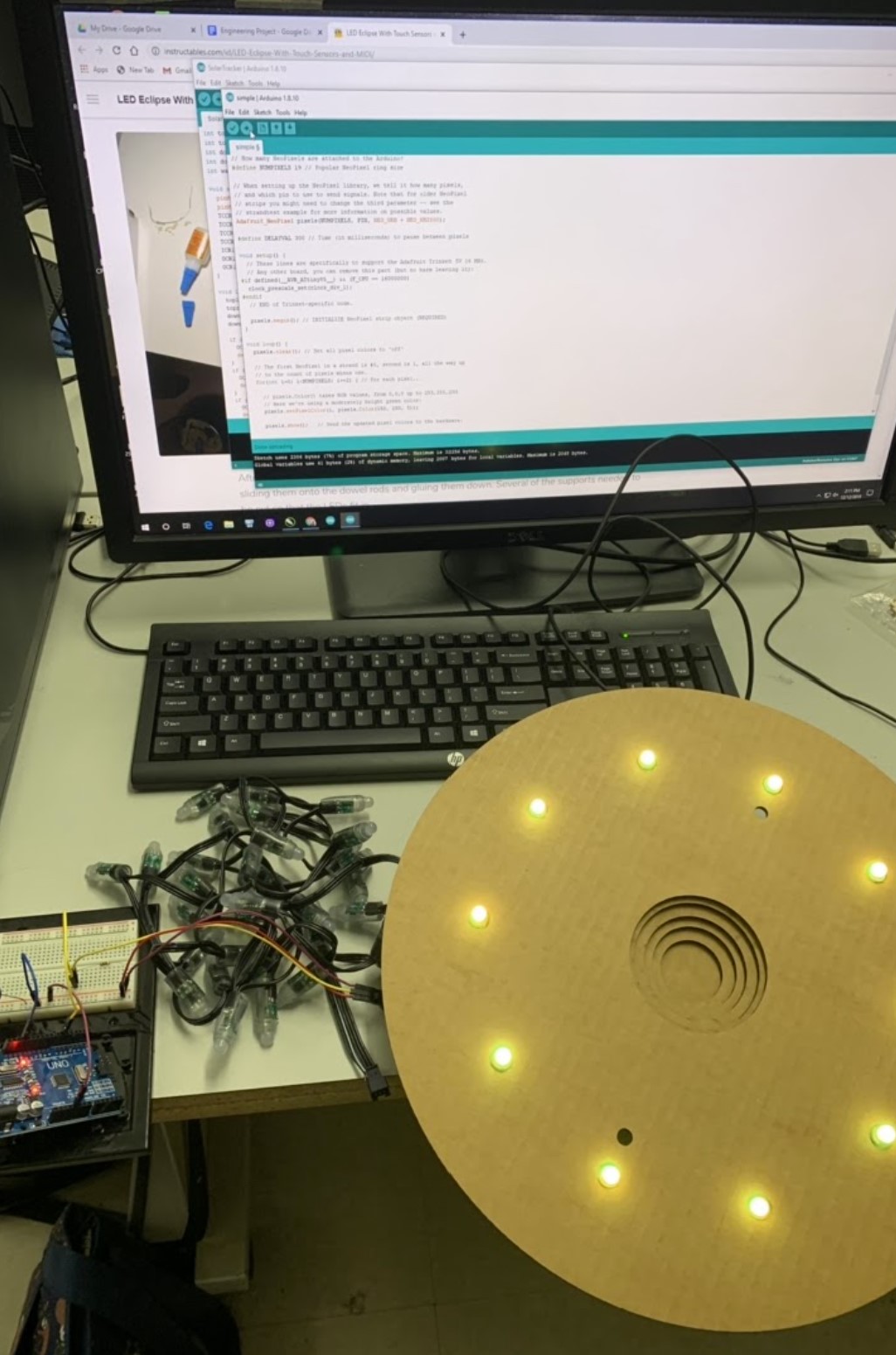
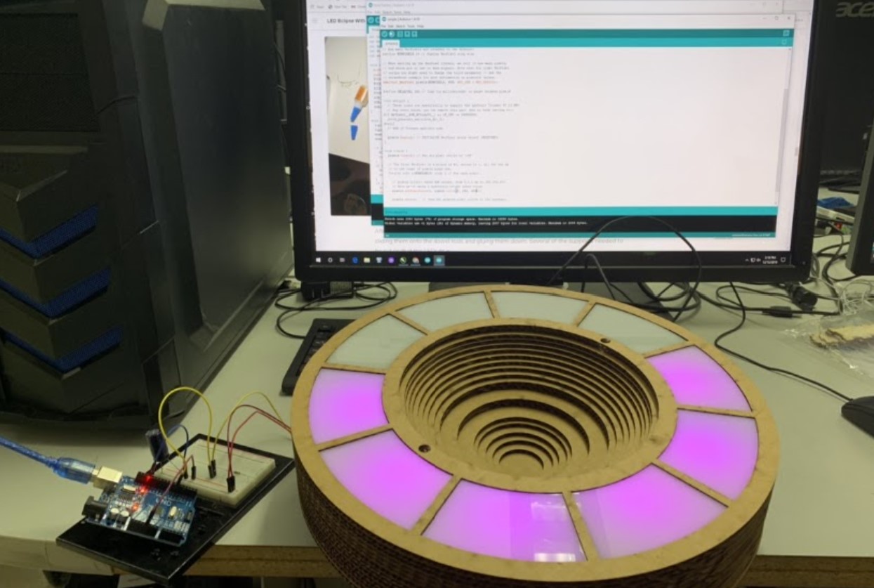
After the LEDs worked with the code, I decided to cut the string LED wire between the 19th and 20th LED, as I did not need the rest of the LEDs after the 19th. This way, I didn’t need to create more storage space in my project to keep LEDs that I was not going to use.
milling and testing capacitive sensors
It was time to move on to the capacitive sensors. I first had quite a learning curve about what they were and how to use them, but after researching about them for a little while I understood how to use them. I decided to use PCBs as sensors, and I milled them in the shape of the curved sections in layer 23. When I milled the first PCB, I realized that it was slightly too big to fit in nicely. I made adjustments and an offset for the milling machine to run so that they would fit better. The first picture below shows the milling of the first sensor, and the second picture shows the milled PCB with the offset lay in layer 23.
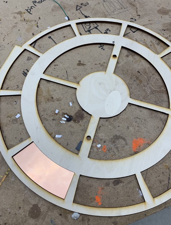
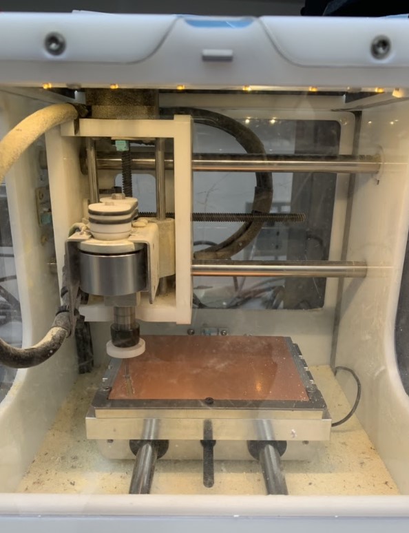
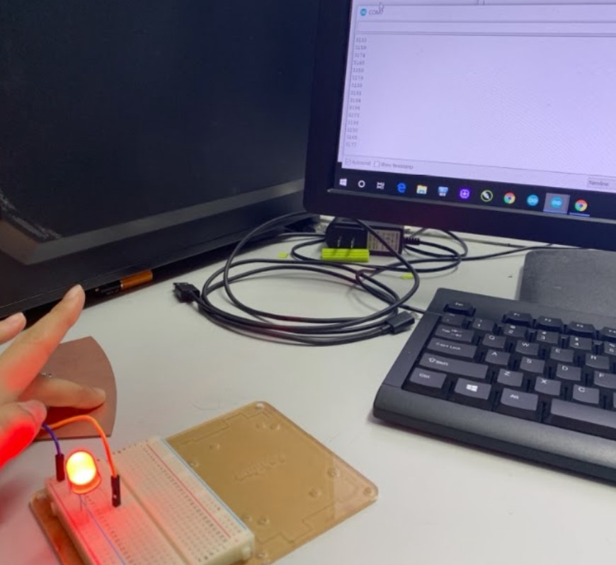
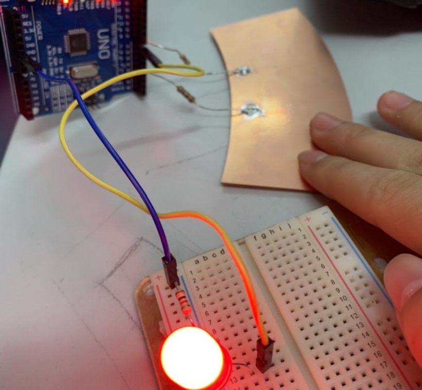
After I milled 10 PCBs that had the offset, I tried to do a proof-of-concept trial with the first PCB that did not fit well into layer 23. I soldered two resistors onto the sensor, a 1M Ohm resistor on the left and a 5.5k Ohm resistor on the right. I connected the 1M Ohm resistor to pin 4, and the other resistor to pin 8. Then, attaching an LED to the Arduino Uno, I found a basic capacitive sensor code that worked. On the serial monitor, no one pressed the sensor, the values on the screen stayed between 1 and 10. When I pressed the sensor, the value shot up to 3000, making the code rather easy to modify and personalize. The picture below to the left shows the code’s serial monitor output value shooting up when I tap on the sensor, and the picture on the right gives a better view of the wiring.
I did encounter some challenges in getting the capacitive sensors to work, though.
The first challenge was that after messing with the code for a little bit and retesting the sensor, I came to a hurdle in the proof-of-concept. The values on the serial monitor updated slowly unless I put my finger behind the pins on the Arduino that the resistors went into. I realized later that it was because I had accidentally initialized and constructed another sensor in the code and that the send pin number in the parameters of the construction did not match up with the same send pin number in the parameters of the sensor I was using. This caused the readings to be muddled. Luckily, I sorted out the code and it worked in the end. The picture below shows the LED working better and having a faster response time with my finger behind the pins of the resistor, functionally acting as another capacitor.
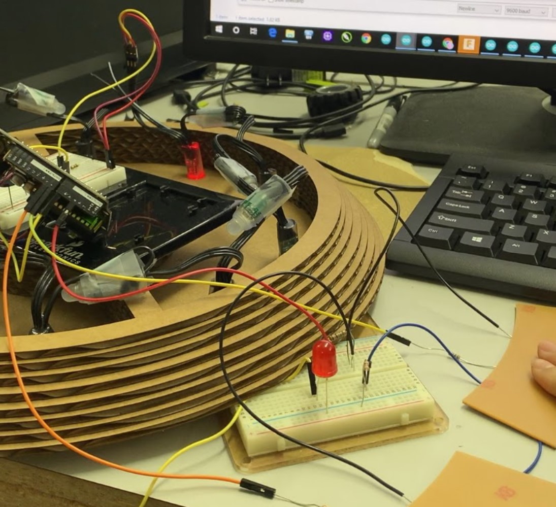
Afterwards, I added to the proof-of-concept with two sensors and the string LED lights to simulate what would happen in the final project with 10. My mistake here was that I had only used one LED pattern, and so I didn’t simulate how the code would differentiate which signal came from what sensor. This error would manifest itself later on in the next challenge I faced as described below, when I superglued all the sensors into layer 23 and wired everything together. The picture to the right shows the double-sensor proof of concept working, as well as the wiring. I overcame this mistake later on when I needed to wire everything together. I went through trials and errors until the code worked in the end.

Afterwards, I soldered the rest of the PCBs and superglued them into each curved section in layer 23.
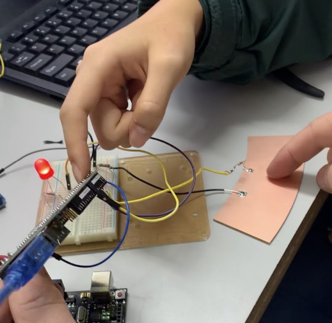
Another challenge I faced was letting all the sensors share a 1M Ohm resistor. I thought that if all the sensors could share resistors, it would not only save materials but it would also prevent the buildup in resistance from sensor to sensor. I didn’t realize this at the time, but after I had changed all the sensors to having direct contact with only one 5.5k Ohm resistor, instead of including the 1M Ohm resistor, it was impossible for the code to recognize which capacitive touch came from what sensor, since the signal would have been shared when going through the resistor. The picture above gives a glimpse of the change; on the right soldered dot, the 1M Ohm resistor had been replaced by a black wire. The pictures below show the wiring of all 10 sensors pre-wired and post-wired. You can see that the black wires all go to share a row with the 1M Ohm resistor.
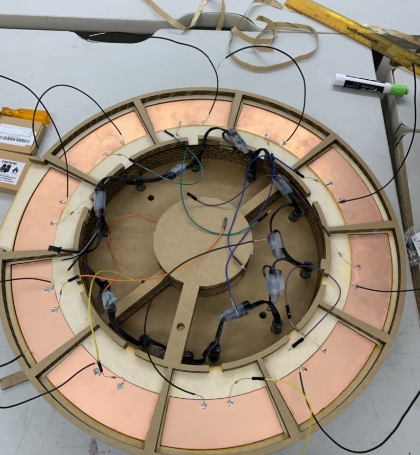
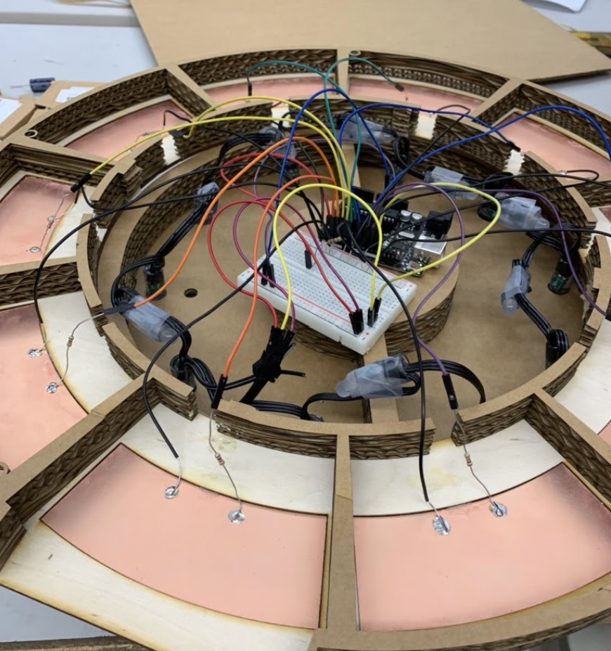
However, at this point, if I wanted to fix the problem I would have needed to re-solder every sensor, but time wouldn’t allow for it. So, I ended up going with the flow of having the same pattern show no matter which sensor you pressed. I had made the code so that when you press a sensor, the lights start from the first light and go around until the last one.
final working project
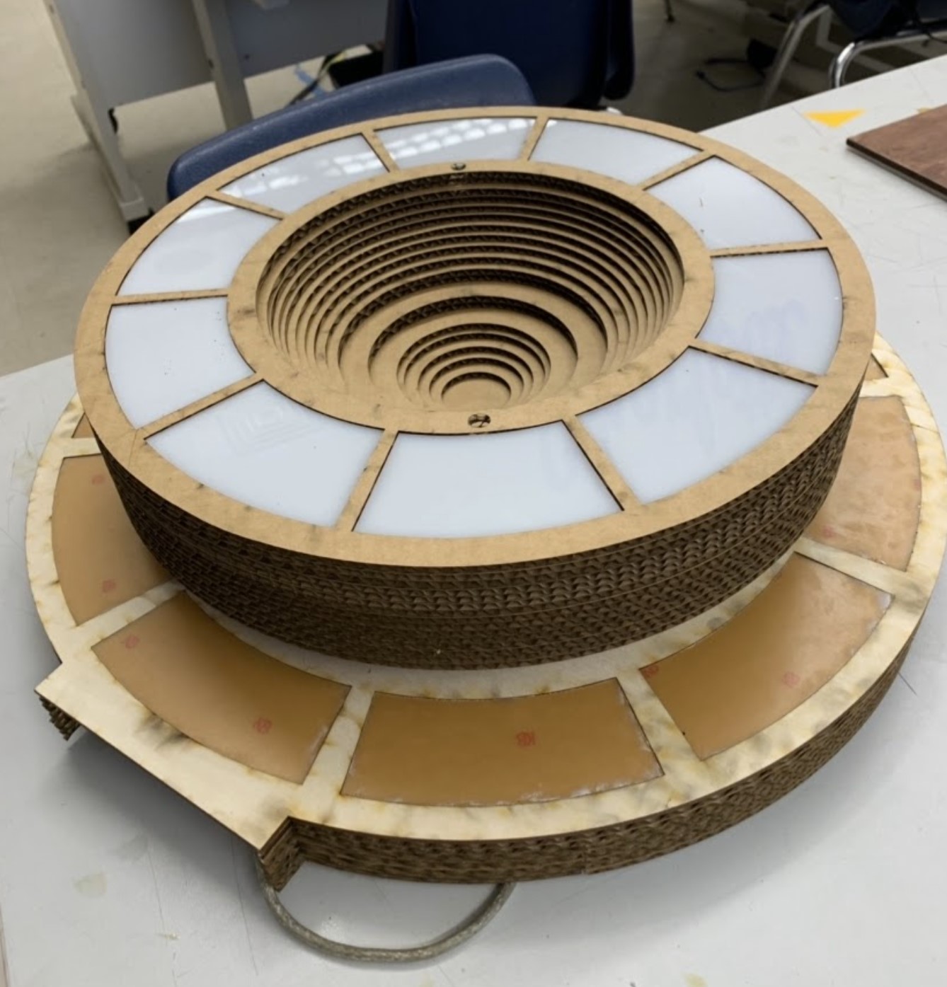
I decided to add more layers at the bottom in order to provide more height to encapsulate the electronics. This way, I did not need to squish the electronics and wire in a small space, and it gave me freedom to position wires in any way I wanted to. I plugged in a longer cord into the Arduino Uno so that I could plug it into a computer from the outside when the final layer was added. I added the final layers, as shown in the picture, and turned it upside down. My project was done. The picture below shows the “Solar” project in action. I decided to name it Solar, after the name of the original, “Eclipse.”

reflection
In making this project, I learned a lot about capacitive sensors, Arduinos, electronics, LEDs, and the process of creating a large project.
This project gave me an opportunity to learn more about capacitive sensors and electronics. I got to experience hands on how to modify certain codes, how to wire relatively more complex diagrams, and how to use capacitive sensors. I learned about send pins and receive pins, and how capacitive sensors work by using the arbitrary value of the amount of time it takes for the receive pin to go into the same state as the send pin. Although looking back it seems obvious, I also learned that capacitive sensors work by allowing another person to be a capacitor; this knowledge will all be substantive when I go about working on my FabAcademy project.
I also learned about the process of creating a large project, and how I work under longer time frame due dates. I learned that I tend to overestimate and over-plan the progress I make in the beginning of an assignment, and that I ought to be more realistic in my planning. I also learned that the finishing touches of a project are actually the hardest parts of a project, and that the home stretch often takes the most amount of time. In this project, I subconsciously focused more on designing each layer and put off working on the capacitive sensors. In retrospect, I learned that I should be more aware of all aspects of a project and should try to balance out how I spend my time on different parts.
If I could spend more time on this project, I would change quite a few things with it. First, starting with the look and design of the project, I would like to size things down a little bit to make it more portable, and would to laser-cut layers in wood to give it a more professional look. Furthermore, I would also re-solder the capacitive sensors so that they each have one 1M Ohm resistor, allowing the code to differentiate which signal comes from what sensor. This way, I would be able to code more colorful and creative patterns for the Eclipse and would be able to specify the origin LED for each run of the pattern. If I had a lot more time, I would even like to incorporate the MIDI aspect back into the project, similar to what it was in the original project. I could make it similar to a speaker that plays and shows different sounds/songs and patterns whenever a specific sensor is pressed. Regardless, I loved making this project and learned so much from it.