Will be documenting the whole process here. Most recent update: Aug 2026; back to it after work and school ended.
context
Whether it was because my mom used to always ask about my skin (and whether I was drinking enough water) or because I over-obsessed about my skin, I used to spend hours of my week leaning over my sink, observing and picking at almost every millimeter and pore of my face. I knew it wasn’t good for me. I knew that the more I picked, poked, and squeezed, the larger my pores would get. The worse my skin would get. But it was so hard for me to stop.
Later, I found out it was likely a subset of skin picking disorder (dermatillomania).
Since high school, I’ve been thinking about making something that would stop me from scrutinizing my face. Now, I want to actually build the thing. So here it is.
Brainstorming
I’ll be at the mirror–washing my hands or face–when I spot something or feel an uneven dot on my face. I’ll then lean close to the mirror (probably within 2 inches) and see if it’s something immediately fixable (ie pick-at-able). Often it is, and so I’ll continue there for a number of minutes, just going at it. I know in my mind that I should stop, but usually I fall into a default state and just keep going.
I think there are a couple of possible inputs and outputs:
Inputs:
- Proximity sensor. I need to get close to pick at my face and see where the imperfections are. (ultrasound? time of flight? many such possibilities)
- Camera for computer vision.
Outputs:
- A mist maker to make my mirror foggy so that I can’t see anything.
- A speaker and annoying voice reminder. I’m usually in that default state when I’m that close to the mirror. And if the only way to stop the voice is to back up, I won’t be able to pick. (broader idea here of a smart home object with light, sound, general ambiance output).
- A bright light. Maybe I just blind myself if I’m really close to the mirror?
- A little OLWD/LCD screen to accompany any of the above possibilities. It can keep track of how many times I’ve picked in the last x amount of time.
- PDLC (polymer dispersed liquid crystal) screen on top of some acrylic (for easy application and removal onto mirrors). This would literally make it so that I can’t clearly see anything. This’ll be a lot easier (and convenient for the user (me)).
V0: Distance sensing, buzzer and PDLC screen output
On this first iteration, I want to focus on building something that will address my core needs: not being able to see my face after picking at my face (getting to close to the mirror).
Electronics:
I’m starting with the core parts needed for an MVP. I’m working with the seeed RP2040, the VL53L1X ToF sensor, a passive buzzer, and the PDLC display.
ToF Sensor Input + Buzzer Output
This was pretty straightforward to build. Just to make sure the overall system would work as expected, I started with Adafruit / packaged versions of everything I needed to start. I found some good Adafruit ToF sensor documentation and worked with the Seeed Xiao RP2040 documentation.
It worked well! Next step: the PDLC film. There was a very immediate first problem: the PDLC film takes in 48-65V (typically works around 50AC/60Hz). And I need to somehow power this from the seeed, which outputs a max of 5V from the rails, or 3.3V from the digital and analog pins.
My first hack-y attempt at a solution was a 5V relay. I’d keep in the batteries, hack open the battery container to reveal where the button switch is, and then solder the relay to those pins such that I could simulate a button press with the output of seeed pin.
PDLC Output
The hack worked! Now to make it look prettier/improve for a v0.1.
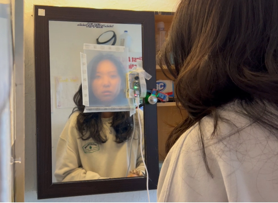
Design
For the first hacky version, I made a case to hold the breadboard, relay, and battery pack that would make testing a little more convenient.
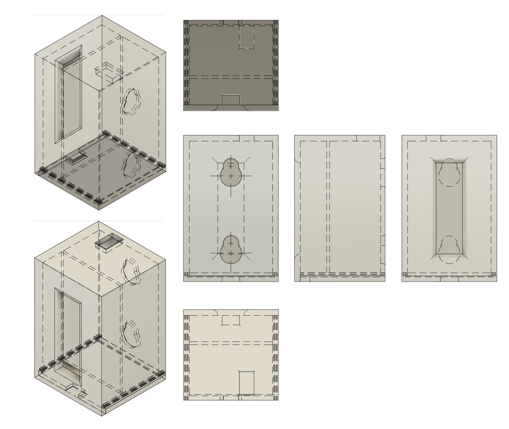
Then it was time to start making a cuter case with my own PCB.
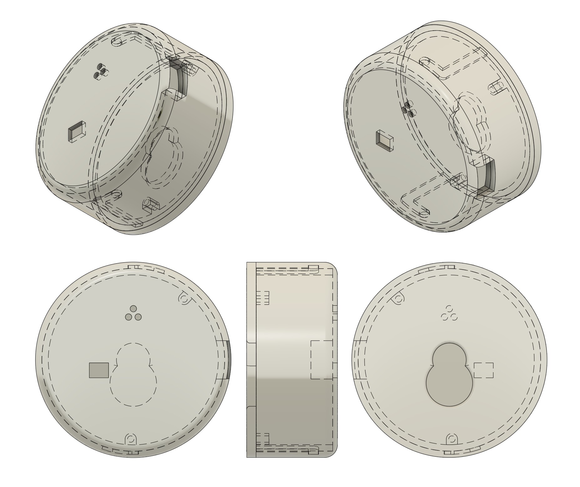
After this version though, I decided to make some changes with the electronics. So back to v0.1 before more CAD.
V0.1: Array Distance sensing, buzzer, PDLC screen output, and an app
I want to make the MCU and detection at least a little bit more robust than a single ToF input. I swapped to the Seeed Xiao ESP32S3 from the RP2040, and to the sparkfun Qwiic ToF Imager from the Adafruit single ToF. I also wanted to replace the relay hack with some proper power considerations. Here was the flow:
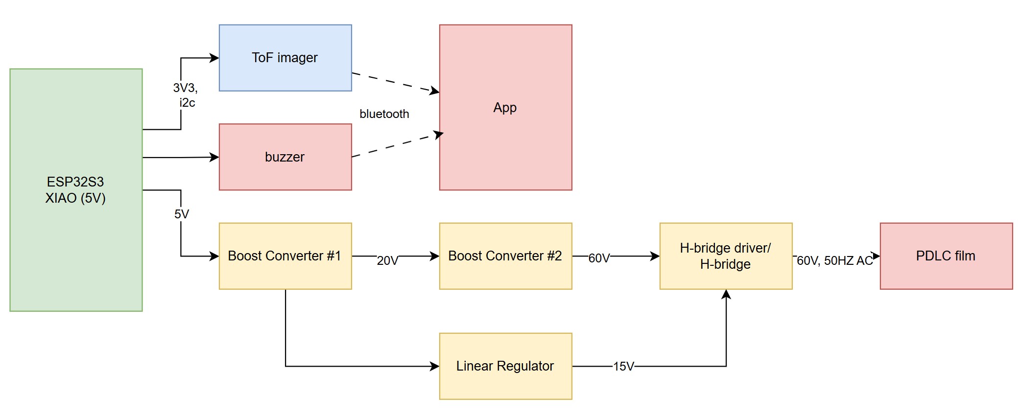
The main thing to add now was the first boost converter from the 5V output pin of the ESP to get 20V. Then that would split into two paths: 1. Another boost converter to get to 60V, then an H-bridge to get the AC needed for the PDLC film, then the PDLC film. and 2. A linear regulator to get a smooth 15V, then to the transistors needed for the aforementioned H-bridge.
Time to buy components! and test!
Design
In my first iteration of design, I wanted to ignore the relay situation. I designed it around the new electronics I was thinking of incorporating, with my own board. (Complete with clearances, a slide and twist fit, and a lot of holes (mounting, ToF, buzzer, USBC, suction cup insert)).
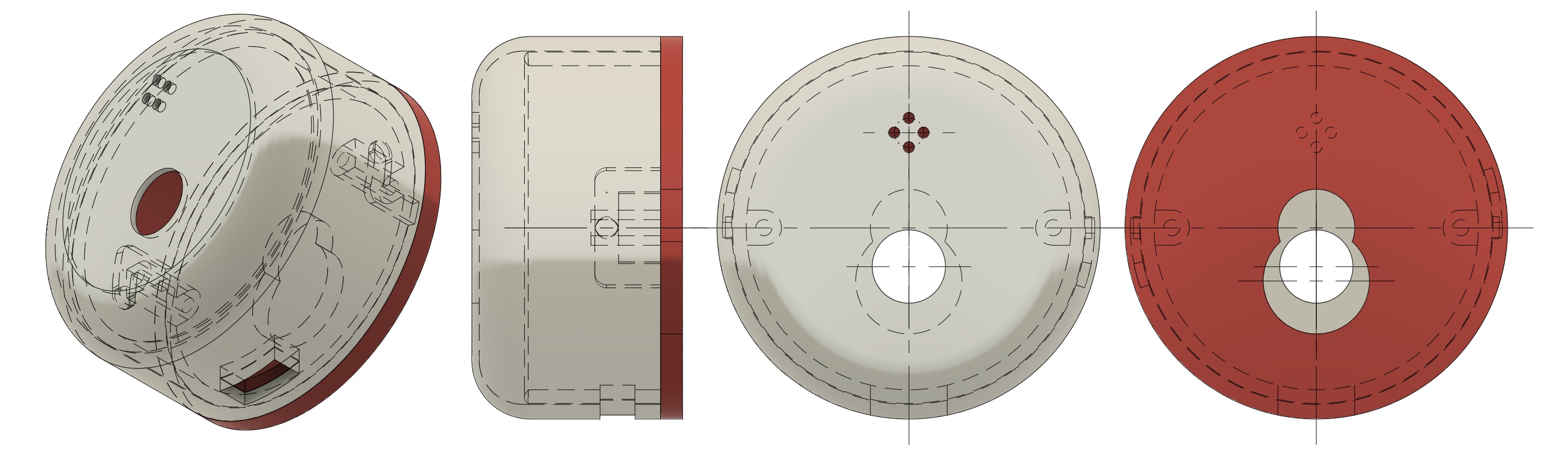
Second iteration incoming with the new electronics.